Building an RFID reader/logger.
For most of the steps in making this circuit you can choose to either do it yourself or have things done for you for a fee. This page and the associated links provide the information you will need to do just about everything yourself, but there are also links to companies that can provide fabrication and assembly services.
Step 1. The board.
You should probably start with the printed circuit board (PCB). If you have never dealt with circuit boards before, better familiarize yourself with them at wikipedia or some similar website. For now, I only present a 2-layer design with mostly surface mount compoents and a minimum of through-hole parts (see wikipedia for explanations of through-hole and surface-mount technology). In the future I hope to provide a single-layer design with mostly through-hole components that can more easily be made by hand. For the current design, I strongly recommend having a PCB fabrication company make your circuit boards. It is possible to fabricate your own circuit boards, and you can use the board images and CAD files below if you want to do this (I leave it to you and Google to discover the abundance of how-to sites for making circuit-boards). However, for this two-layer or two-sided design, I'm going to assume that you do not want to set up a PCB fabrication lab. So here are some options:
Batch PCB. If you just want one or two boards, and you don't mind waiting a couple of weeks, you can order boards via www.batchpcb.com. This service accumulates orders from lots of customers and then produces them in one big batch every few weeks. This makes it fairly cheap to get small boards or just one or two of a particular item. I have loaded the design into batchpcb, and you can access and purchase it here for about $18 per board.
PCB fabrication company. If you want more boards and a lower per board price, then you can avail yourself of numerous PCB manufacturers. Two such companies are Advanced Circuits and ExpressPCB, but there are lots of them out there if you care to shop around. Advanced Circuits offers a "bare bones" PCB deal which can deliver from one up to a few hundred boards in a day or two for a fairly low price. But you will not get the lettering and symbols printed on the top with the "bare bones" deal (i.e. they won't do the silkscreen). ExpressPCB offers a special that gets you three boards for $51. Of course most of the expense in making boards is getting everything set up. If you want to make tens or hundreds of boards, you should probably just make a regular "full spec" order with the company of your choice. The more boards you get, the lower the cost per board. For example, if you get 200 or so boards, you can expect the price to be about $4 per board. To use one of these companies, you will need to download the zipped gerber file from the link below (right click and select "save link") to submit with your order.
Low cost reader PCB files. The board-image pdf can be printed to make your own boards. The eagle files are CAD files that can be opened in the free version of Eagle CAD. The gerber files are for submitting fabrication jobs to PCB manufacturers. To see the Gerber files, download them, unzip them, and view them with the online gerber viewer.
Monochrome Board images (pdf) ---- Eagle files (Schematic; Board file)--- Zipped gerber files.
Step 2: Purchase parts
In addition to circuit boards, you will need a bundle of electronic components. I have posted an annotated partslist with part numbers and potential vendors for each component. Note that some of the parts are optional. Please read the notes in the partslist to determine whether you want to buy the optional parts.
Step 3: Assembling surface mount components
The surface mount assembly can be done by an assembly company, but it is simple enough that you can do it yourself if you don't mind a bit of tedium. To do your own surface mount assembly, you will probably want to use solder paste and a toaster oven. Solder paste is a viscous form of metal solder that can be applied to a circuit board via a large hypodermic needle or with a stencil. Once the solder paste is applied to the board, you place the surface mount component onto their solder pads and then bake the board in the toaster oven to melt the solder and fuse the parts to the board. For a tutorial on this process, click here. Zephyr paste is a good choice for solder, and it comes in convenient syringes. Applying the solder with a syringe can be rather tedius, especially when the parts count is a few dozen. The alternative is to buy a stencil that you can lay down over the PCB and then smear the paste over the stencil to apply it to the solder pads (described in the above mentioned tutorial). I recommend OHARARP for fast cheap stencils made of polyimide (Kapton) film ($25 plus shipping). To get a stencil made you will need to download the zipped gerber files, unzip them and use the file called "GP_READER2.GBP," which specifies solder pad locations and shapes. For this circuit, which uses mostly large components, you can also just print the circuit onto some transparency film, get a small hole punch (I have a 1/16" hole punch from Wal-mart), and punch holes where the solder pads are to make your own stencil. Use this assembly guide (pdf) to help you place your parts.
The alternative is to have a PCB assembly company do the work for you. If you get your boards made by Advanced Circuits they can also do assembly for you. Just ask them for a quote. You could also try the online quote system at Screaming Circuits. Depending on how many boards you have made the cost will be around $8 to $20 per board for surface-mount assembly.
Step 4: Through-hole assembly
Although the pcb assembly companies mentioned above can deal with through-hole parts, they generally have to do it by hand, which means high labor costs. Given the small number of through-hole parts in the RFID reader design and the simplicity of the design, it is probably much more cost effective to do the through hole assembly yourself. Even if you have never soldered anything before, you can probably learn this skill very quicky (my six-year-old learned it in about 5 minutes). If this stuff is new to you, Google will find you numerous web pages to teach you through-hole soldering. The basic tools are a soldering iron (a $15 one from the hardware store will do) and some rosin core solder. Use the assembly guide (pdf) and the printing on the top of the circuit board to guide your part placement. note that the IC's, the clock battery, and the large electrolytic capacitors are polar, so maker sure the postive and negative leads go in the correct holes. The holes for the clock battery are designed to accomodate several types of battery holders, so not every hole may be used. If you use the inexpensive battery from Arrow electronics with the leads already attached, you will have to bend one lead flat to make the battery fit the holes.
Many of the through-hole parts are optional. Refer to the partslist to see what is optional and to read about why or why not to install these parts
Step 5: Programming the microprocessor
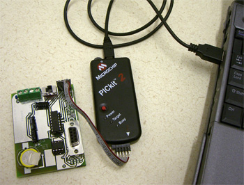
The microprocessor (a PIC16F688) integrates all of the components on the circuitboard and carries out serial communication with a computer. Of course, the device doesn't know how to do all of this straight from the factory, so you have to program it to behave properly. You can program the PIC in one of two ways: 1) plug the PIC into a programming device and then place it on the PCB, or 2) place the PIC on the circuitboard and program it via in circuit serial programming (ICSP). For either technique you will need a programming device. My favorite is the PicKit 2, which can be purchased for about $25 if you shop around. There are numerous others out there including kits and instructions for building your own. A professional (expensive) programmer is not necessary.
Here is how to program a PIC with a PicKit 2 (if you use another programmer the process should be similar:
1. Install the current version of the MPLAB Software, and download (right click and save) this text file (GP_Reader2_3.hex) and store it someplace where you can find it later.
2. Open MPLAB and Plug in the PicKit 2. If you want to use a programming socket to program the PIC off the RFID circuitborad, then plug in the socket and put the PIC in the correct spot within the socket (see photo).
INSERT IMAGE HERE
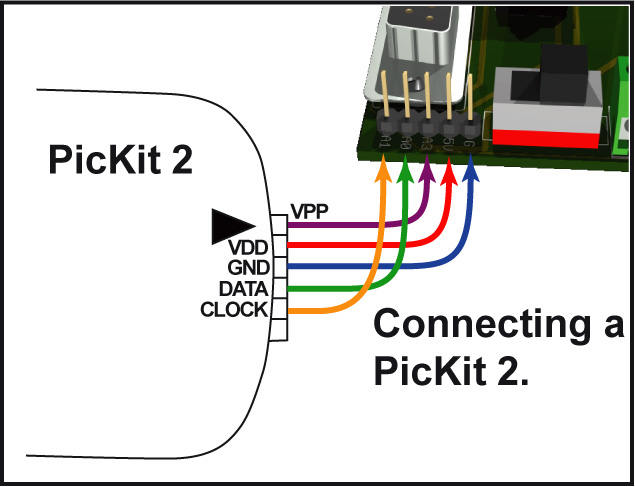
To do ICSP, attach the PicKit 2 to the 5-pin Header (one of the optional through-hole parts), and make sure that the PIC is in place on the board (soldered in or in the IC socket). To attache the PicKit 2 to the board you will need to build a 5 wire jumper with a plug on one end and a socket on the other. Note that not all of the lines on this jumper can go parallel (see photo and diagram below).
3. In MPLAB, under configure click on "select device" and find "PIC16F688" in the list. Then click through "programmer-->select programmer-->Pickit 2." If everything is set up correctly, MPLAB will spit out a message that says the programmer is online and that a PIC16F688 has been detected.
4. Under "file" select "import" and browse to the text file you downloaded (GP_reader2_3.hex).
5. Click through "programmer-->program," and if all is well you should see messages that programming and verification are proceeding.
That's it. To program additional PICs, simply change out the PIC or plug into another board and click through "programmer-->program."
Step 6: Initial testing of the circuit board
Once you have the circuit board assembled and programmed, you may want test it to see if it works before moving on. Attache a 12-16V power source to the battery terminals on the circuit board (either solder the leads or use the optional screw clamps). Follow the instructions in the manual to establish serial communication with a PC. When you first turn the reader you should see the main menu message. You can now test the clock and settings. Reading tags will not work at this point because there is no antenna attached. Which brings us to....
Step 7: Antennas
The reader works with loop antennas (a tight coil of enamel-coated wire) wound such that the inductance is right around 1.35mH. There are some notes on making antennas in the manual. Below are some examples of jigs for making your own antennas. You can also make an antenna by simply winding wire around a wood or plastic frame. Note that you should not have any metal objects near the antenna when testing the inductance or reading tags.
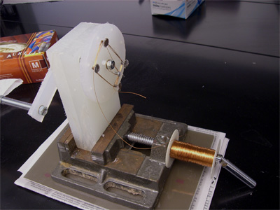

Joe Casto's Antenna winder (read the pdf).
When you have wound an antenna, you should probably coat it with epoxy or some other rugged adhesive. This coating should both hold the coil together and protect it from the elements
When the antenna is ready, strip the enamel off the two ends of the coil and attach them to the "ANT" terminals on the circuit board--either solder the leads in place or use the optional screw clamps. You can now carry out a full test.
Step 8. Final testing
You should now be able to carry out all the functions described in the manual.
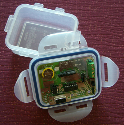
Step 9. Housing
The circuitboard will probably need some sort of housing, especially if you plan to use the reader outdoors. If you round the corners of the board with a file or belt sander, the circuit should fit into the lid of a 1.8oz lock-n-lock box, with just enough room for a pack of 8 AAA batteries. You will proabably need to customize your housing to fit your individual circustances and battery requirements. When designing houseing, bear in mind the need for a waterproof container that allows the antenna wires and perhaps the battery leads to extend out of the box. You can do this with lock-n-lock boxes by simply running the thin enameled wire over the edge of the container (The o-ring around the lid creates a seal even with the wire passing under it).